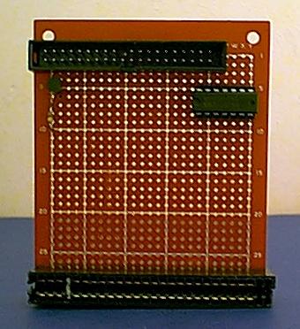
When the +3e was first released back in 2000, using a hard disk with a Spectrum was a relatively new idea. There were no ready-built hard disk interfaces, but two schematics were available on the web, both designs by Pera Putnik. One of these was a very simple and easy-to-construct 8-bit interface, whilst the other was a more complex full 16-bit design. The +3e used the simple 8-bit interface (with some slight addressing modifications). This is the interface which is described below.
Several years on, and there are now a wide variety of hard disk and compactflash interfaces available for the Spectrum. Some can be bought ready-built, as kits or unpopulated PCBs, or as schematics for the enthusiast to build their own. The +3e supports all known available interfaces - if you find any that aren't supported, please contact me.
The +3e now even supports interfaces using the MMC protocol, which means really tiny interfaces can be made, accepting MMC or SD cards (typically used in digital cameras, PDAs and mobile phones etc).

Following are are some links for the supported interfaces. Note that some of these interfaces can run other software/firmware as well as the +3e ROMs; you can generally use both the +3e ROMs and the "native" firmware, since the +3e does not interfere with any special interface facilities (such as extra RAM and ROM).
The classic interface for the +3e! Build it yourself, as described below. Some people have built this as an internal interface that plugs into the Z80 CPU socket, with the Z80 itself "piggy-backed" on top. Steve Smith produced some PCB designs for both internal and external versions, which are archived here. José Leandro has produced some PCBs for a compactflash-based version.
Updated July 2017! Steve Smith has re-designed his PCB in KiCad, and the new boards look really smart. Download the files here:
Updated October 2017! Klaudiusz Fatla has provided some great-looking images of an internal version, together with schematic and Gerbers, available here:
Because of the simplicity of this interface, there are very few components or connections required, so most people with access to a soldering iron should be able to construct it without too many problems.
Thanks to Frans van Egmond for details of the internal interface provided here (although neither he nor I accept any responsibility for any damage caused by the interfaces presented here).
PLEASE NOTE: I cannot build interfaces for other people!
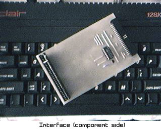
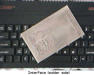
Here is a photo of the interface that I built, and use with my +3e:

Thanks must go here to Pera Putnik, who designed the original "simple" IDE interface; the interface presented here is almost identical, with just a couple of changes to the addressing, which should allow the interface to be compatible with more other hardware.

You will need the following components to make the IDE interface:
Additionally, you will need a small board to mount the circuit on.
If you wish to build the popular internal interface, instead of the Spectrum edge connector you will require a 40-pin socket for the Z80 chip (with long legs if you can find one). In this case, the Z80 is removed from its socket and plugged into the interface card socket; the whole thing is then plugged into the Z80 socket in the +3.

A schematic for the interface is shown below. Unlike most schematics, I have included all the connections you need to make, so you do not need to know much about electronics to build the interface; you just need to be able to use a soldering iron. Colour-coding is used where confusion might otherwise arise.
Pin numbers for both the Spectrum and IDC connectors are listed. Additionally, connections for the Z80 socket are given if you wish to build an internal interface, rather than an external one. For the Spectrum connector, these correspond to the diagram at the back of the +3 manual. For the IDC connector, pins are numbered 1,3,5...39 along one side of the connector, and 2,4,6...40 along the other, with pins 1 & 2 being adjacent. For the Z80 socket, if you look at the chip with the notch at the top, pins are numbered 1-20 down the left side, and 21-40 back up the right side to the top.


Steve Smith has spent some time producing some PCB layouts for both the internal and external 8-bit interfaces. The external interface he has built from this looks very smart! If you're able to produce your own PCBs, Steve has kindly provided full details of this and layout files in several formats, together with some nice pictures of the interface and his final setup.
Grab the entire archive (layouts, instructions and piccies) in this file: Plus3eHD_Int.zip. In the meantime, here are some pics of the final product to whet your appetite!


