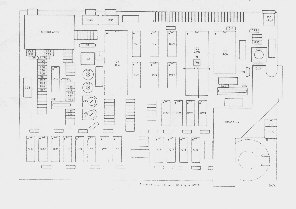
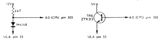
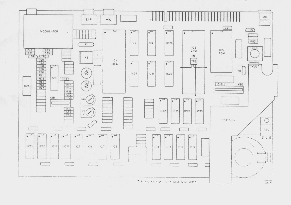
Servicing Sinclair Computers Part 5 Previous treatment of the Spectrum in this series has related specifically to the issue 3 and 3B versions. There has however been continuous development of the machine since its introduction in 1982. The range now extends from the initial issue 1 version to issue 6A, covering a total of eight models with six PCB changes. It's time we looked at some of these variants, starting with the earlier models. The issue 1 and 2 versions have a lot in common. They both have the early zig-zag shaped heatsink, and both have small trimmer capacitors and preset potentiometers for setting up the colour generator circuits. The issue 2 board layout is shown in fig. 8. The issue 1 differs only in the design of the original 32K extension memory, which isn't assembled on the main board as with all later versions. Instead, its built on a plug-in board that carries the memory ic' s and the decoders and multiplexers. This daughter board plugs into two DIL sockets at the rear of the main board and extends right across from the modulator to the coil. To accommodate this, the CPU and the multiplexer chips IC3/4 are moved towards the front of the main board along with the ULA and ROM chips, leaving a clear space on which the extension memory board fits. If this space isn' t filled the machine isn' t worth very much, since the extension is no longer available and without it the majority of the commercial programs cannot be used. Another distinctive feature you will find on some Issue 1 boards is the "spider". Due to a timing error in the 5C102 ULA chip it was necessary to fit an extra 74LS(X) i.c. Because this was added retrospectively there wasn' t room for it on the board, so the i.c. had to be mounted on its own small board suspended above the main board by the connecting wires. When the later type 5C112 ULA was introduced the spider was no longer required. The initial issue 2 board used the same 5C112 ULA but a further modification was fitted: this was the addition of TR6 which replaced the previous diode/resistor network - see Fig. 9. As you can see from Fig. 8. TR6 is mounted across the top of the CPU i.c. Later versions of the issue 2 board have the current 6C001 ULA chip: this necessitated some resistance changes which are detailed in (4) of the issue 2 modification instructions.
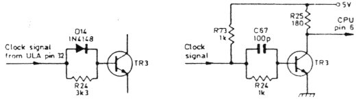
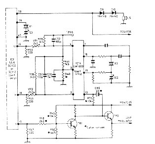
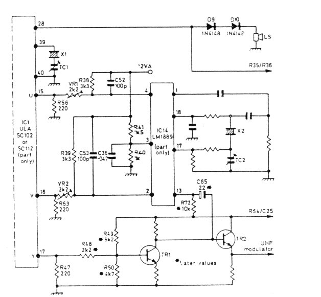
The following modifications should be added whenever a Spectrum is dismantled for servicing. First. issue 1 versions. Issue 1 Modifications (1) When National 4116 RAM i.c.s are fitted, remove R57 (330ohm) - connected to pin 28 of IC2 - and fit a lkohm resistor between the CAS line and the 12v rail and another 1kohm resistor between the RAS line and the 12v rail. These resistors are best fitted on the underside of one of the memory chips IC6-13. C54 (at pin 3 of IC2) can also be removed - but it must be left in circuit when the 4116 RAMs are of NEC manufacture. (2) When a type 5C102 ULA is fitted. add a 100pF capacitor between the RAS line and chassis. (3) C46 (1uF electrolytic) should be replaced with a high-temperature capacitor it' s mounted beneath the heatsink. (4) Axial capacitors should be fitted in place of all the disc ceramic capacitors. The following capacitors must he replaced: C41 (ROM pin 14 to pin 28) and C49 (between the collector and emitter of TR4) - these capacitors are both 47nF. (5) If there' s insufficient colour difference between white and yellow, fit a 47kohm resistor between pin 13 of IC14 (LM1889) and chassis. (6) To improve the reliability of the voltage generator the circuit should be modified to correspond with Fig. 13. A minimum would be to change the value of R60 and fit a 4.7uF electrolytic (C74) between the emitter and base of TR5. See the notes on this section of the circuit in Part 6 next month. (7) Finally, if you want to use the Spectrum to operate a Z80 PIO, or if you find that some machine code software doesn' t run satisfactorily, check that the following modifications have been made. (a) Change TR3s base circuit as shown in Fig 10. i.e. replace D14 with C67, change R24 to Ikohm and add the pull-up resistor R73. (b) Change R27 from 680ohm to 47oohm or shunt it with a I.5kohm resistor (ULA pin 33 to CPU pin 20). Issue 2 Modifications Now to issue 2 boards. Like the modifications given for the issue 1 version these should be made whenever possible. Fig. 8 shows the positions of the components. (1) Replace all disc ceramic capacitors with axial ones. Especially change C41 an d C49 (47nF) - as with issue 1 boards - and change C43 (100nF) in the voltage generator circuit. This, together with modification (3) below will update the circuit almost to issue 3 standard. (2) To improve the colour, change R48S to 2.2kohm. R49 to 8.2kohm. R50 to 4.7kohm. R72 to 10kohm and C65 to 22uF. These components are all associated with the luminance/chrominance drives to TR1 and TR2 (see Fig. 11). (3) Carry out the same modifications as those listed under (6) and (7) for issue 1 boards. (4) The only currently available ULA is type 6C001. When this is used to replace an earlier type the following modifications should be made: change R47 to lkohm. R49 to 10kohm and R56 and R63 to 470ohm. (5) There' s no need to change the speaker circuit from that shown in Fig. 5 to that shown in Fig. 11. The modification is very simple however if increased sound Output is require. Servicing Aspects From the servicing point of view the advice given to issue 3 versions applies in general to issue 1 and 2 versions. There' s one exception. There are four presets- (TC1. TC2, VRI and VR2) that may need setting up if any changes have been made. Their positions are show in Fig. 8 and their functions are as follows. TC1 sets the frequency of the 14MHz crystal that controls all the computer timing, including the 50Hz field sync signal. You might think that this would provide an easy means of setting up this control, but in many cases the range of adjustment is too small to enable the 50Hz to be locked. The control is used only to alter the frequency slightly, to eliminate any objectionable colour patterning on the screen. TC2 sets the frequency of the colour subcarrier oscillator and unlike TC1 Sinclair advise precise adjustment using a frequency counter. I' ve personally had no problems with the setting of this control but if a check is required it should be possible to compare the results with the frequency obtained from a TV set locked to a transmitter. VRI and VR2 are the only controls that may present difficulties. They affect the phasing of the colour-difference signals and are interactive in their effect on the display. Take particular care when dealing with issue 1 models because although the controls are in the same positions and are marked as shown in Fig. 8, the connections between them and IC14 are reversed. A colour display is necessary for setting and checking these controls. The following short program will display colour bars, enabling the effect of any changes to be seen across the colour spectrum. It' s advisable to sav e this program to make it easier to load when the top case and keyboard are lifted to reach the presets. 10 FOR N = 0
T0 7 This will display the Spectrum colours corresponding to keys 0 to 7. ie. black, blue, red, magenta, green, cyan, yellow and white. If there is no colour on the screen when this program is entered and run, check the TV sets tuning and colour controls. If there' s still no colour the controls will have to be set up. The procedure suggested by Sinclair is as follows. (1) Switch on and initialise the computer. Do not enter a program. (2) Using TC2. set the colour subcarrier frequency to 4.433619MHz +/- 50Hz (3) Using VR1. set the voltage at pin 4 of IC14 to 50rnV + 0mV/-5mV relative to pin 3. (4) Using VR2. set the voltage at pin 2 of IC14 to -50mV +5mV/-50mV relative to pin 3. These settings are designed so that pins 2 and 4 will be at zero with respect to pin 3 when the computer is at its operating temperature. In the factory however they set pin 4 to 130mV +/- 20mV and pin 2 to -75mV +/- 20mV, so you can take your choice which values to use.
Personally I prefer the following method of setting these controls. It may seem very complex at first sight but it's actually quite simple. A word of explanation. Those of you who are long in the tooth - and short of hair - may remember ion traps. These could be set in a few seconds but it took you twice as long even to read the Mullard instructions. This procedure is similar. As the settings aren't critical - about the same as the average hold control - getting the colour correct is easier than reading the instructions. So here they are: (1) Load the program above and run it. (2) Assume that the subcarrier frequency is o.k. and set VR1/2 to mid-travel. (3) Slowly sweep VR1 until colour is displayed. If no colour shows during the full travel of VR1 , move VR2 slightly and try again. (4) Keep moving VR2 in steps of about 20-30 degrees, sweeping VR1 slowly back and forth until colour has been obtained, or the whole range of both potentiometers has been covered. (5) If no colour can be obtained at any settings, mark the position of the vanes of TC2 and move it approximately 30 degrees. Repeat (3) and (4) above. At worst it should take only about four- five repeats to get some indication of colour. (6) When some colour is displayed, move the presets one at a time until the full eight colour bars are present, in their correct colours. Finally find the optimum position for each adjustment, going over TC2, VR1 and VR2 at least twice. The colour controls should now be set up correctly and the bars displayed in their correct colours. Check by switching channels on the TV set and making sure that the colours lock without any delay. When all is well set TC1 as described below. If you still have a problem there could be a fault in IC14, the associated circuitry or the signals from the ULA. The colour-difference signals can be checked either at pins 17 and 18 of the edge connector (underside) or at VR1 and VR2. Examination of the signals with and without the colour display running will show if the ULA is o.k. Check the oscillator and its frequency at pin 17 of IC14 - use a high-impedance probe when checking the frequency. Finally, when a satisfactory colour display has been obtained put in a program giving a screen full of characters in red ink with a background of green paper and adjust IC1 for minimum patterning. Some early machines have a hole in the bottom of the case to enable this adjustment to be carried out with the computer fully assembled. Next month well deal with the 4A, 4B, 5 and 6A versions. |
| [ Main Page ] [ Features ] |